- 您现在的位置:买卖IC网 > Sheet目录335 > ISL97672BIRZ (Intersil)IC LED DRVR BACKLIGHT 20QFN
�� �
�
�ISL97672B�
�(EQ.� 1)�
�I� LEDmax� =� ---------------�
�R� SET� =� 410.5� ?� 0.02� =� 20.52k� Ω�
�Theory� of� Operation�
�PWM� Boost� Converter�
�The� current� mode� PWM� boost� converter� produces� the� minimal�
�voltage� needed� to� enable� the� LED� stack� with� the� highest� forward�
�voltage� drop� to� run� at� the� programmed� current.� The� ISL97672B�
�employs� current� mode� control� boost� architecture� that� has� a� fast�
�current� sense� loop� and� a� slow� voltage� feedback� loop.� Such�
�architecture� achieves� a� fast� transient� response� that� is� essential�
�for� notebook� backlight� applications� in� which� drained� batteries�
�can� be� instantly� changed� to� an� AC/DC� adapter� without�
�noticeable� visual� disturbance.� The� number� of� LEDs� that� can� be�
�driven� by� ISL97672B� depends� on� the� type� of� LED� chosen� in� the�
�application.� The� ISL97672B� is� capable� of� boosting� up� to� 45V� and�
�typically� driving� 13� LEDs� in� series� for� each� of� the� 6� channels,�
�enabling� a� total� of� 78� pieces� of� the� 3.2V/20mA� type� of� LEDs.�
�Enable�
�Device� is� enabled� if� the� Enable� pin� voltage� is� high.� If� EN� is� pulled�
�low� for� longer� than� 30μs,� the� device� will� be� shutdown.� The� Enable�
�pin� should� not� float;� a� 10k� or� higher� pull-down� resistor� should� be�
�connected� between� EN� and� GND.�
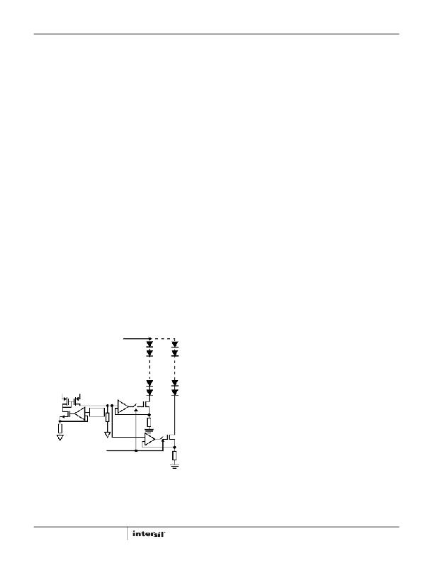
�Current� Matching� and� Current� Accuracy�
�Each� channel� of� the� LED� current� is� regulated� by� the� current�
�source� circuit,� as� shown� in� Figure� 20.�
�The� LED� DC� current� is� set� by� translating� the� R� SET� current� to� the�
�output,� with� a� scaling� factor� of� 410.5/R� SET� .� The� source� terminals�
�of� the� current� source� MOSFETs� are� designed� to� run� at� 500mV� to�
�optimize� power� loss� versus� accuracy� requirements.� The� sources�
�of� errors� of� the� channel-to-channel� current� matching� come� from�
�the� op� amp’s� offset,� internal� layout,� reference� and� current� source�
�resistors.� These� parameters� are� optimized� for� current� matching�
�and� absolute� current� accuracy.� The� absolute� accuracy� is� also�
�affected� by� the� external� R� SET� .� A� 1%� tolerance� resistor� should� be�
�used.�
�Dynamic� Headroom� Control�
�The� ISL97672B� features� a� proprietary� Dynamic� Headroom�
�Control� circuit� that� detects� the� highest� forward� voltage� string� or�
�effectively� the� lowest� voltage� from� any� of� the� CH0� through� CH5�
�pins.� When� this� lowest� channel� voltage� is� lower� than� the�
�short-circuit� threshold,� V� SC� ,� this� voltage� is� used� as� the� feedback�
�signal� for� the� boost� regulator.� The� boost� adjusts� the� output� to� the�
�correct� level� such� that� the� lowest� channel� pin� is� at� the� target�
�headroom� voltage.� Since� all� LED� stacks� are� connected� to� the�
�same� output� voltage,� the� other� channel� pins� will� have� a� higher�
�voltage,� but� the� regulated� current� source� circuit� on� each� channel�
�ensures� that� each� channel� has� the� same� current.� The� output�
�voltage� regulates� cycle� by� cycle,� and� it� is� always� referenced� to� the�
�highest� forward� voltage� string� in� the� architecture.�
�Dimming� Controls�
�The� ISL97672B� allows� two� ways� of� controlling� the� LED� current,�
�and� therefore,� the� brightness.� They� are:�
�1.� DC� current� adjustment�
�2.� PWM� chopping� of� the� LED� current� defined� in� Step� 1.�
�MAXIMUM� DC� CURRENT� SETTING�
�The� LED� DC� current� of� each� channel� can� be� calculated� as� shown�
�in� Equation� 1:�
�410.5�
�R� SET�
�For� example,� if� the� maximum� required� LED� current�
�(I� LED(max)� )� is� 20mA,� rearranging� Equation� 1� yields� Equation� 2:�
�(EQ.� 2)�
�PWM� CURRENT� CONTROL�
�The� ISL97672B� employs� direct� PWM� dimming� such� that� the� output�
�PWM� dimming� follows� directly� with� the� input� PWM� signal� without�
�modifying� the� input� frequency.� The� average� LED� current� of� each�
�channel� can� be� calculated� as� shown� in� Equation� 3:�
�I� LED� (� ave� )� =� I� LED� � PWM�
�(EQ.� 3)�
�Switching� Frequency�
�The� boost� switching� frequency� can� be� adjusted� by� connecting� a�
�resistor� between� FSW� pin� and� GND.� The� calculation� of� the�
�resistance� is� shown� in� Equation� 4:�
�(� 5� � 10�
�)�
�f� SW� =� -----------------------�
�+�
�-�
�REF�
�+�
�-�
�10�
�R� FSW�
�(EQ.� 4)�
�RSET�
�+�
�where� f� SW� is� the� desirable� boost� switching� frequency,� and� R� FSW�
�is� the� setting� resistor�
�PWM� DIMMING�
�-�
�5V� Low� Dropout� Regulator�
�There� is� an� internal� 5V� low� dropout� (LDO)� regulator� to� develop� the�
�necessary� low-voltage� supply,� which� is� used� by� the� chip’s� internal�
�FIGURE� 20.� SIMPLIFIED� CURRENT� SOURCE� CIRCUIT�
�9�
�control� circuitry.� VDC� is� the� output� of� this� LDO� regulator� which�
�requires� a� bypass� capacitor� of� 1μF� or� more� for� the� regulation.�
�The� VDC� pin� can� be� used� as� a� coarse� reference� as� long� as� it� is�
�sourcing� only� a� few� milliamps.�
�FN7995.1�
�November� 22,� 2013�
�发布紧急采购,3分钟左右您将得到回复。
相关PDF资料
ISL97675IRZ-TK
IC LED DVR PWM CTRL 4CH 20QFN
ISL97677IRZ
IC LED DVR PWM CTRL 8CH 32QFN
ISL97678IRZ
IC LED DVR PWM DIMMING 8CH 32QFN
ISL97686IRTZ
IC LED DRVR BACKLIGHT 28TQFN
ISL97691IRTZ-TK
IC LED DRVR BACKLIGHT 3D 16TQFN
ISL97693IRTZ-TK
IC LED DRVR BACKLIGHT 16TQFN
ISL97901CRZ
IC LED DRVR 1.5A 28QFN
ISO1I811T
ISOLAT DGTL 500VAC 8CH 48TSSOP
相关代理商/技术参数
ISL97672BIRZ-T
功能描述:IC LED DRVR BACKLIGHT 20QFN RoHS:是 类别:集成电路 (IC) >> PMIC - LED 驱动器 系列:- 产品培训模块:Lead (SnPb) Finish for COTS
Obsolescence Mitigation Program 标准包装:2,500 系列:- 恒定电流:- 恒定电压:- 拓扑:升压(升压),切换式电容器(充电泵) 输出数:1 内部驱动器:是 类型 - 主要:背光 类型 - 次要:白色 LED 频率:625kHz ~ 875kHz 电源电压:2.7 V ~ 5.3 V 输出电压:5V 安装类型:表面贴装 封装/外壳:10-TFSOP,10-MSOP(0.118",3.00mm 宽) 供应商设备封装:10-µMAX 包装:带卷 (TR) 工作温度:-40°C ~ 85°C
ISL97672IRZ
制造商:Intersil Corporation 功能描述:6-CH LED DRIVER WITH PWM DIMMING - Rail/Tube 制造商:Intersil 功能描述:6-CH LED DRVR W/PWM DIM
ISL97672IRZ-T
制造商:Intersil Corporation 功能描述:6-CH LED DRIVER WITH PWM DIMMING, T&R - Tape and Reel 制造商:Intersil 功能描述:6-CH LED DRVR W/PWM DIM
ISL97672IRZ-TK
制造商:Intersil Corporation 功能描述:6-CH LED DRIVER WITH PWM DIMMING, 1K T&R - Tape and Reel 制造商:Intersil 功能描述:6-CH LED DRVR W/PWM DIM 1K
ISL97673IRZ
制造商:Intersil Corporation 功能描述:6-CH LED DRIVER WITH SMBUS OR PWM DIMMING AND PHASE SHIFT CO - Rail/Tube 制造商:Intersil 功能描述:6-CH LED DRVR W/SMBU OR PWM DIM & PHS
ISL97673IRZ-T
制造商:Intersil Corporation 功能描述:6-CH LED DRIVER WITH SMBUS OR PWM DIMMING AND PHASE SHIFT CO - Tape and Reel 制造商:Intersil 功能描述:6-CH LED DRVR W/SMBU OR PWM DIM & PHS
ISL97673IRZ-TK
制造商:Intersil Corporation 功能描述:6-CH LED DRIVER WITH SMBUS OR PWM DIMMING AND PHASE SHIFT CO - Tape and Reel 制造商:Intersil 功能描述:6-CH LED DRVR W/SMBU OR PWM DIM & PHS
ISL97674IRZ
制造商:Intersil Corporation 功能描述:6-CH LED DRIVER W/ PHASE SHIFT CNTRL + FRAME RATE & DIMMING - Rail/Tube 制造商:Intersil 功能描述:6-CH LED DRVR W/PHS SHFT CNTRL + FRM RTE